Interaction
Diagrams
Last updated:
May 24, 2006
Objectives:
-
Define classes and their
characteristics
-
Define the two types of interaction
diagrams and their importance to realizing use cases identified in the
use-case model
-
Identify the inputs and elements
necessary to create the interaction diagrams
-
Use the Rose tool to add classes and
their characteristics to the model
-
Create interaction diagrams to show
the interaction between objects
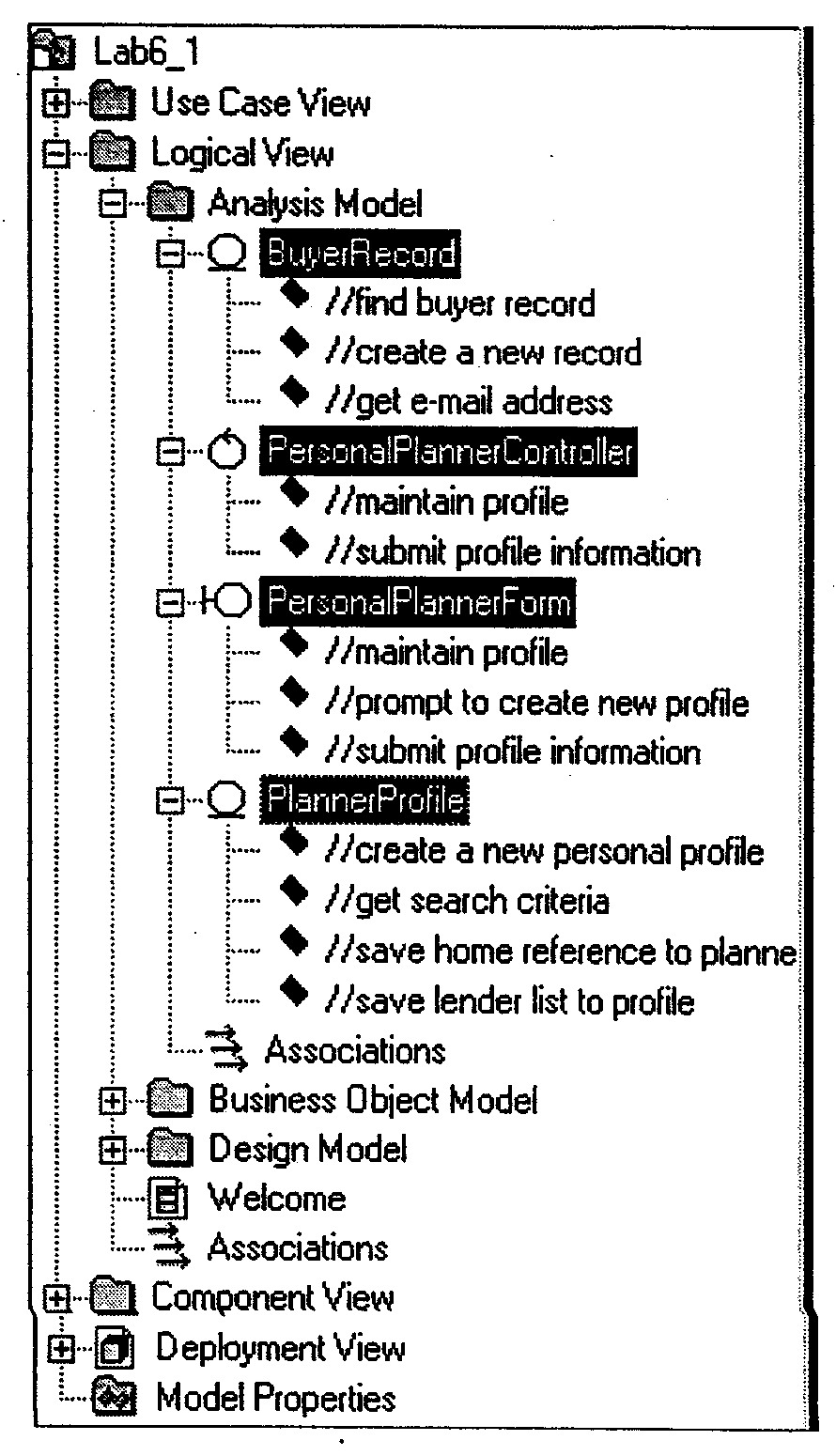
Class Responsibilities:
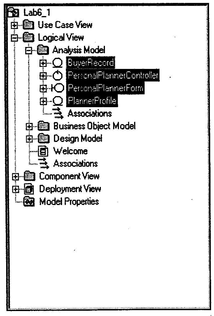
Add Analysis Classes:
Interaction Diagrams:
-
Interaction diagrams are modeled in
the Logical View under the appropriate use-case realization
-
In Rose, you can activate Sequence
numbering from the Options window. It is not a default because the location
of the arrows show the relative sequence of events
-
In sequence diagrams, actors who
initiate an action generally appear on the left side. Passive actors appear
to the right side of the diagram
-
The focus of control is set up from
the Diagram tab in the Options window. It is a default in Rational Rose. If
you don't want the focus of control to display on your sequence diagrams, go
to the Options window to turn off the feature.
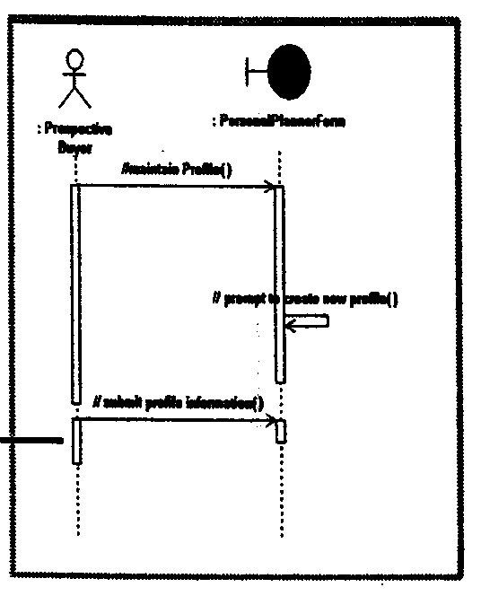
Create a Sequence Diagram:
-
Add Sequence Diagram
to the Browser
-
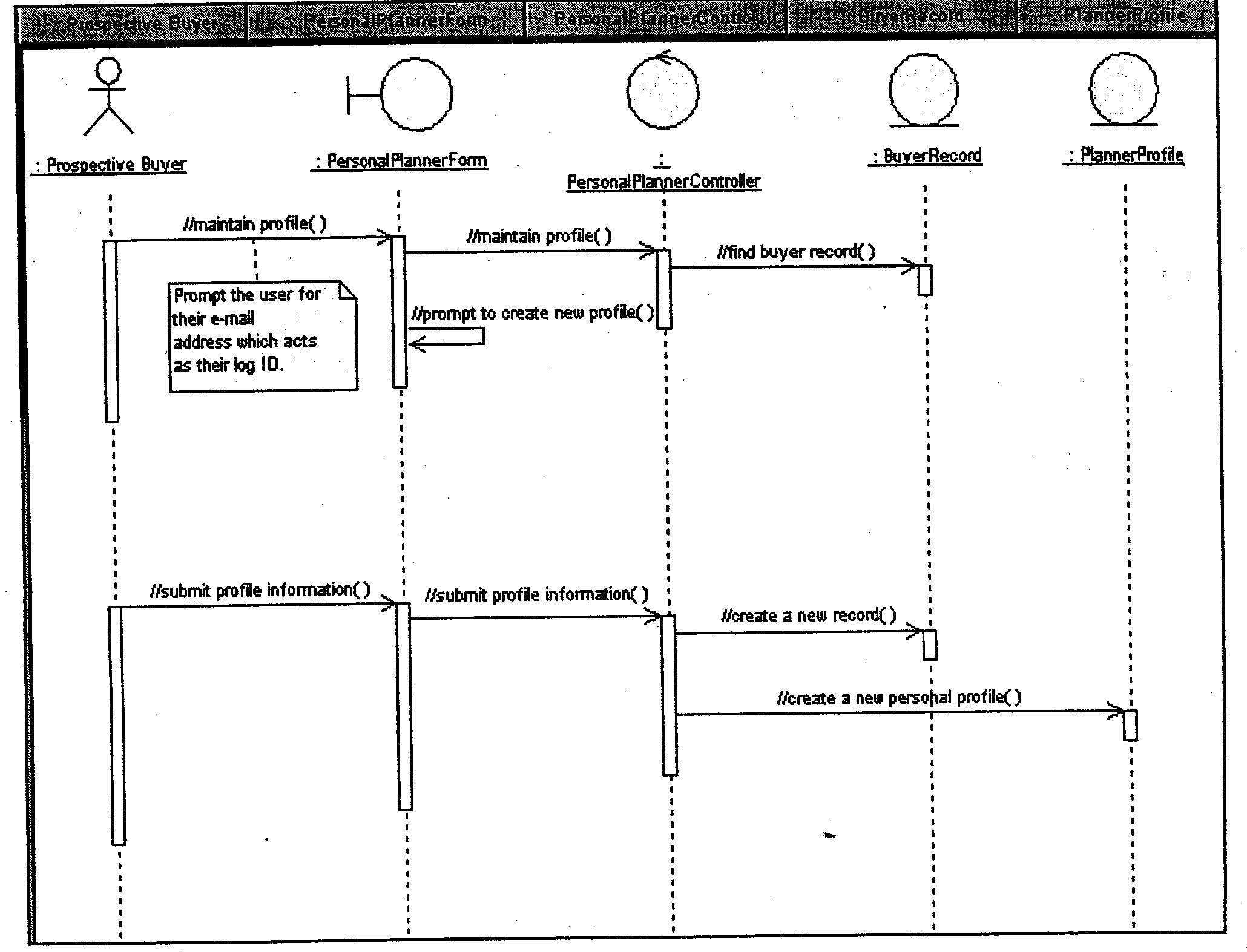
Add Actor and classes:
-
Add Object Messages:
-
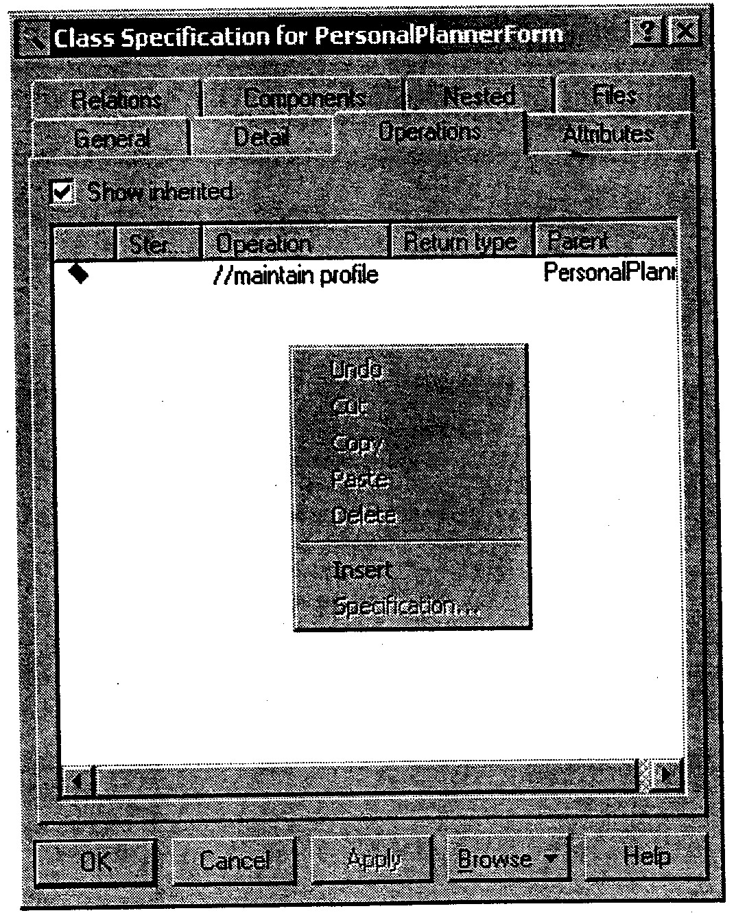
Add Responsibilities
to Object Messages:
-
Add the note and the anchor
Show Unresolved Objects:
Show Unresolved Messages:
Documentation Report:
-
You can generate this report for
any Rose diagram created in either the Logical or Component View
-
This report generates a formatted
Microsoft Word document of the logical or Component View of a selection
-
The Documentation Report generates
a data dictionary from a model using Microsoft Word OLE Automation
objects
Auto Generate a
Communication Diagram:
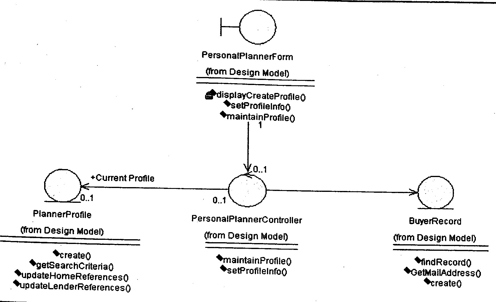
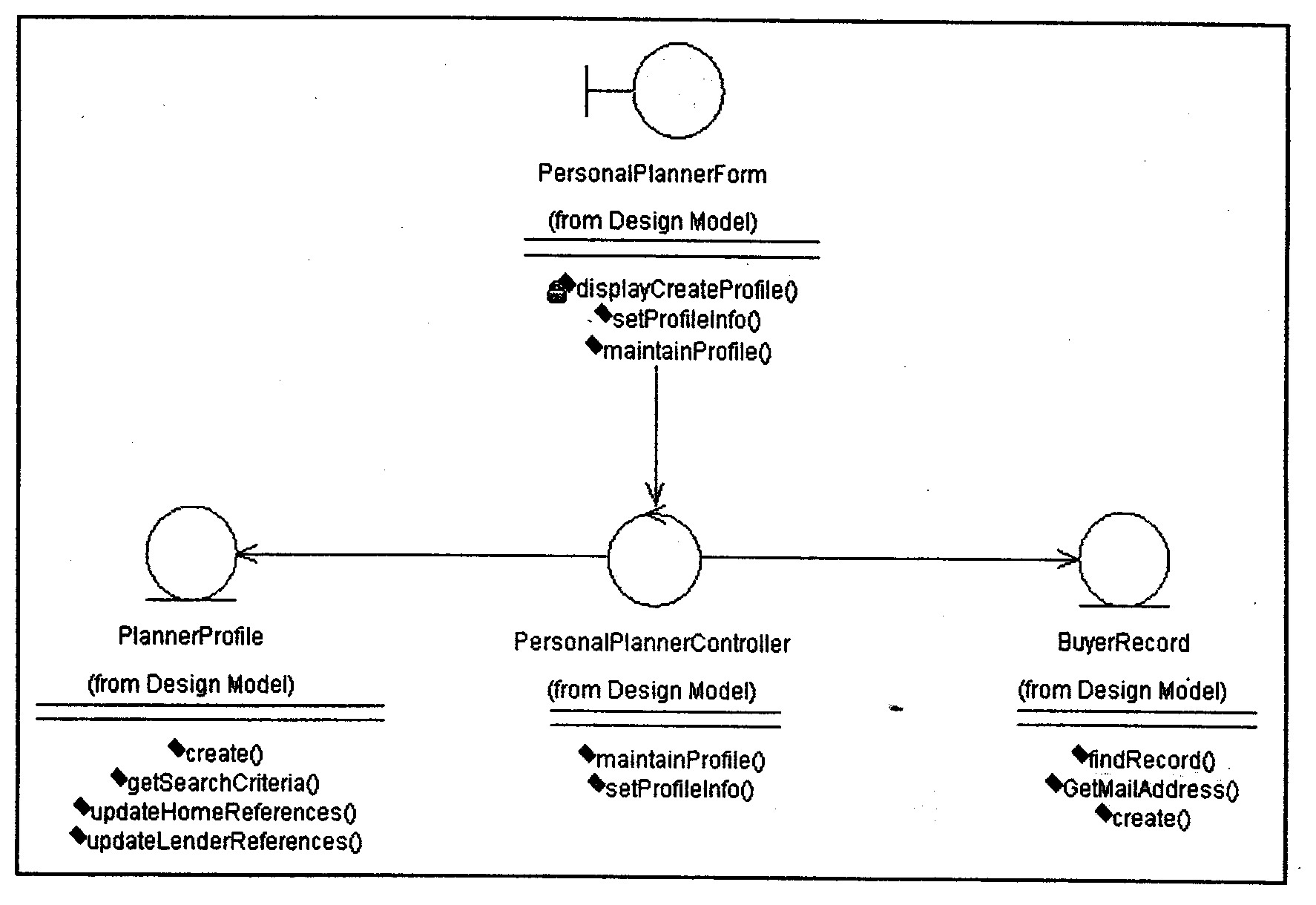
VOPC Class Diagrams:
-
A VOPC class diagram shows a use-case
realization's participating classes and the relationships among those
classes
-
It shows all classes whose instances
collaborate to perform the use case and their relationships
-
It ensures consistency in use-case
implementation across subsystem boundaries
-
Like interaction diagrams, there is
one class diagram associated with each flow through a use case. It's just a
shift in focus. You'll now concentrate on classes and their relationships,
not objects and their relationships
-
Interaction diagrams represent the
dynamic view of the system, and class diagrams represent the static view
-
Do not include actors on your class
diagrams. They exist outside the system, and you are modeling the system
itself
-
They are modeled in the Logical View
and show the static view of the system
-
Role Names:
-
Role names preferable to
association names when sufficient information is available
-
Role names should always be used
during design
-
Note that Rational Rose
automatically places a symbol next to the role name to indicate how the
class and its elements are seen outside the package where the class is
defined. Examples are public (+), private (-), protected (#), and
implementation (no symbol).
-
Show Access
Violations:
-
An access
violation occurs when a class in one package references a class in
another package in the absence of an import relationship between the two
packages. The following represent Export Control values in Rose
(Association Specification window)
-
Public: The element is visible
outside of the enclosing package and you can import it to other portions
of your model. Operations are accessible to all clients
-
Protected: The element is visible
to any of its descendants
-
Private: The element is visible
only to itself or elements nested within it
-
Implementation: The element is
visible only in the package in which it is defined. An operation is part
of the implementation of the class
-
An access violation also occurs
when a package references a class from another package, whose export
control is set to Implementation
-
The Show Access Violations report
lists all access violations between packages in a class diagram
-
Show Instances:
Create a Class Diagram:
-
Add Class Diagram to
the Browser:
-
Add Classes to the
Diagram:
-
Add Associations:
-
Use the communication diagram to
determine the relationships between classes
-
From the diagram toolbar in the
class diagram: Click the Unidirectional Association icon -> Drag the
mouse from the sending class to the receiving class
-
Add Role Names and
Multiplicity:
-
Double-click the association to
open the Association Specification Window
-
From the General tab: Type Current
Profile in the Role A field -> Click the Role A Detail tab to add Role
A's multiplicity
-
From the Multiplicity list, click
0..1
-
Click the Role B Detail to add
Role B's multiplicity
-> From the Multiplicity list, click 0..1