Packaging Tips: Boundary Classes
-
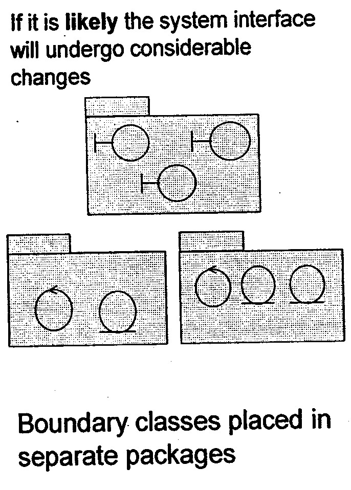
If it likely that the system interface will be replaced, or undergo considerable changes, the interface should be separated from the rest of the Design Model. When the user interface is changed, only these packages are affected. An example of such a major change is the switch from a line-oriented interface to window-oriented interface.
-
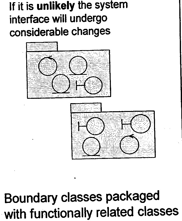
If no major interface changes are planned, changes to the system services should be the guiding principle, rather than changes to the interface. The boundary classes should then be placed together with the entity and control classes with which they are functionally related. This way, it will be easy to see what boundary classes are affected if a certain entity or control class is changed.
-
Mandatory boundary classes that are not functionally related to any entity or control classes, should be placed in separate packages, together with boundary classes that belong to the same interface.
-
If a boundary class is related to an optional service, group it in a separate subsystem with the classes that collaborate to provide the service. The subsystem will map onto an optional component that will be provided when the optional functionality is ordered.
Packaging Tips: Functionally Related Classes
-
A package should be identified for each group of classes that are functionally related
-
There are several practical criteria that can be applied when judging if two classes are functionally related. These are, in order of diminishing importance.
-
If changes in one class' behavior and/or structure necessitate changes in another class, the two classes are functionally related.
-
It is possible to find out if one class if functionally related to another by beginning with a class-for example, an entity class-and examining the impact of it being removed from the system. Any classes that become superfluous as a result of a class removal are somehow connected to the removed class. By superfluous, we mean that the class is only used by the removed class, or is itself dependent upon the removed class.
-
Two objects can be functionally related if they interact with a large number of message, or have an otherwise complicated intercommunication.
-
A boundary class can be functionally related to a particular entity class if the function of the boundary class is to present the entity class.
-
Two classes can be functionally related if they interact with, or are affected by changes in, the same actor. If two classes do not involve the same actor, they should not lie in the same package. The last rule can, of course, be ignored for more important reason.
-
Two classes can be functionally related if they have relationships between each other (associations, aggregations, and so on). Of course, this criterion cannot be followed mindlessly but can be used when no other criterion is applicable.
-
A class can be functionally related to the class that creates instances of it.
-
-
These two criteria determine when two classes should not be placed in the same package:
-
Two classes that are related to different actors should not be placed in the same package.
-
An optional and a mandatory class should not be placed in the same package.
-
Package Dependencies: Package Element Visibility
-
Visibility can be defined for package elements the same way it is defined for class attributes and operations. This visibility allows you to specify how other packages can access the elements that are owned by the package.
-
The visibility of a package element can be expressed by including a visibility symbol as a prefix to the package element name.
-
There are three types of visibility defined in the UML:
-
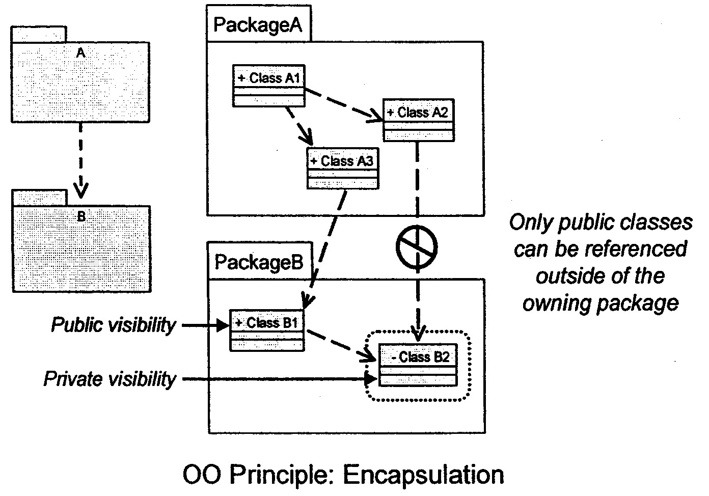
Public: Public classes can be accessed outside of the owning package. Visibility symbol: +.
-
Protected: Protected classes can only be accessed by the owning package and any packages that inherit from the owning package. Visibility symbol: #.
-
Private: Private classes can only be accessed by classes within the owning package. Visibility symbol: -.
-
-
The public elements of a package constitute the package's interface. All dependencies on a package should be dependencies on public elements of the package.
-
Package visibility provides support for the OO principle of encapsulation.
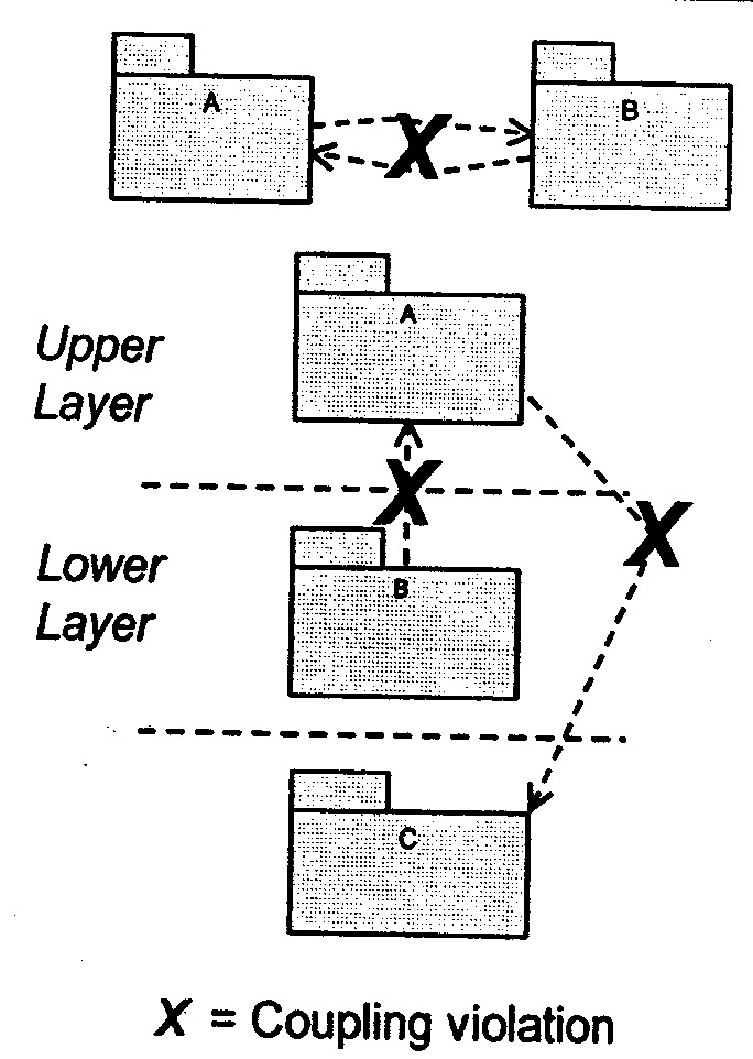
Package Coupling: Tips
-
Package coupling is good and bad: Good, because coupling represents re-use, and bad, because coupling represents dependencies that make the system harder to change and evolve.
-
Some general principles can be followed:
-
Packages should not be cross-coupled (that is, co-dependent); for example, two packages should not be dependent on one another. In these cases, the packages need to be reorganized to remove the cross-dependencies.
-
Packages in lower layers should not be dependent upon packages in upper layers. Packages should only be dependent upon packages in the same layer and in the next lower layer. In these cases, the functionality needs to be repartitioned. One solution is to state the dependencies in terms of interfaces, and organize the interfaces in the lower layer.
-
In general, dependencies should not skip layers, unless the dependent behavior is common across all layers, and the alternative is to simply pass through operation invocations across layers.
-
Packages should not depend on subsystems-only on other packages or on interfaces.
-
Packaging decisions for the Course Registration System:
-
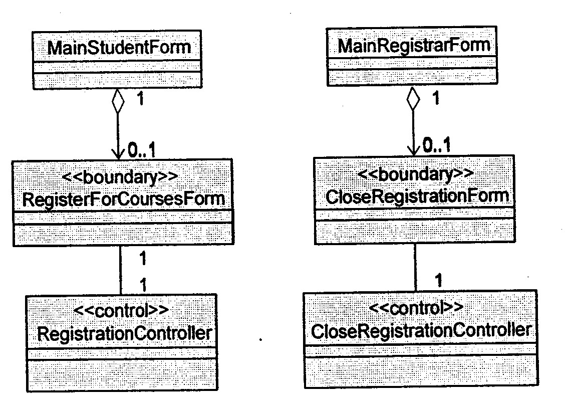
Example: Registration Package
-
All classes specifically supporting registration were partitioned into the Registration package.
-
-
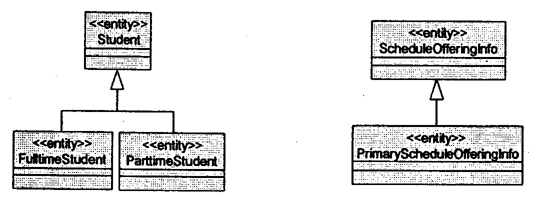
Example: University Artifacts Package: Generalization
-
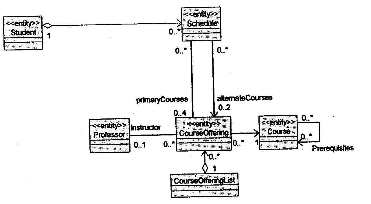
Example: University Artifacts Package: Associations
-
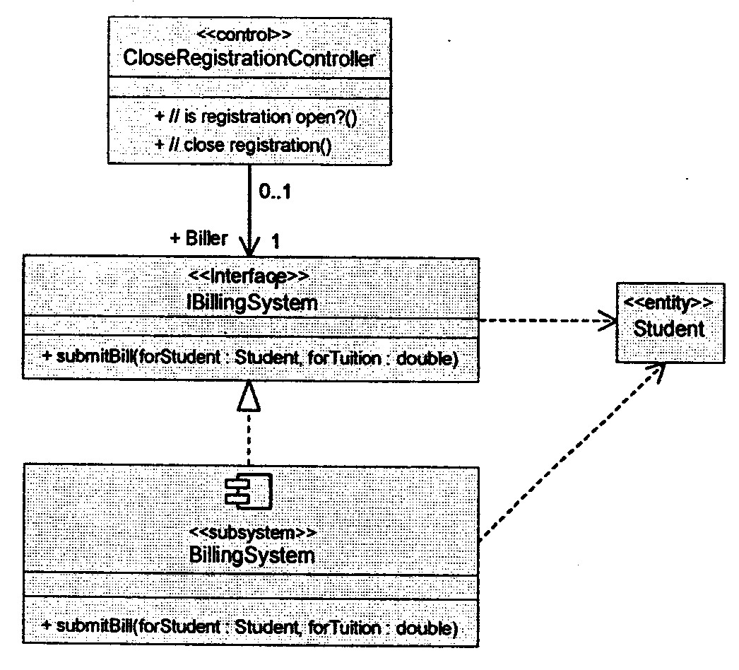
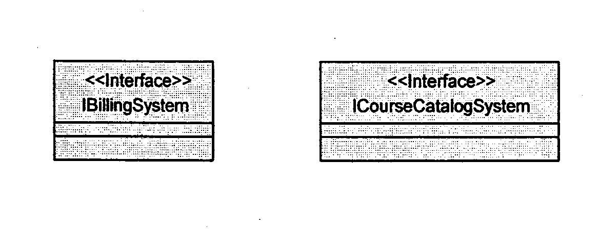
Example: External System Interfaces Package
-
The external system access classes were partitioned into the External System interfaces package. This is so that the external system interface classes can be configuration-managed independently from the subsystems that realize them.
-
Subsystems and Interfaces:
-
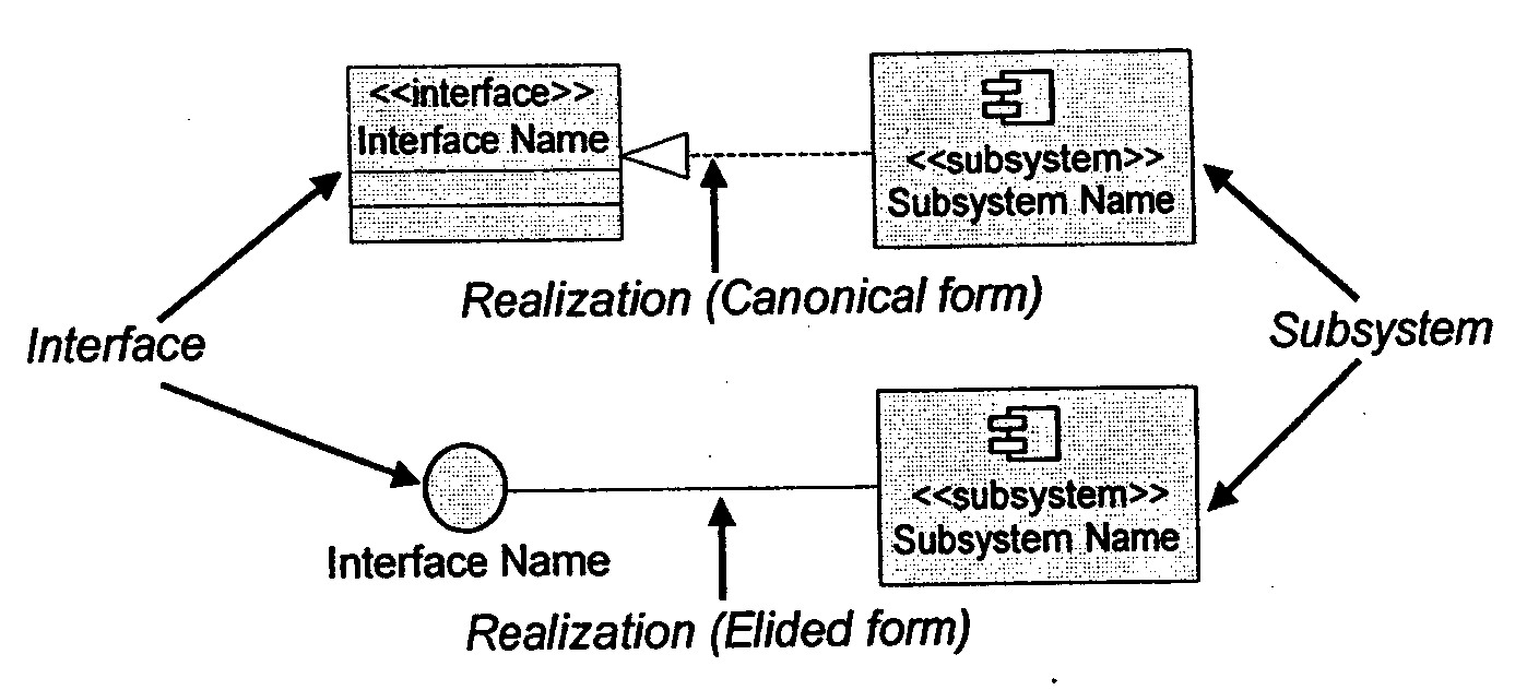
A subsystem is model element that has the semantics of a package, such that it can contain other model elements, and a class, such that it has behavior. A subsystem realizes one or more interfaces, which define the behavior it can perform.
-
An interface is a model element that defines a set of behaviors (a set of operations) offered by a classifier model element (specifically, a class, subsystem, or component). The relationship between interfaces and classifiers (subsystems) is not always one-to-one. An interface can be realized by multiple classifiers, and a classifier can realize multiple interfaces.
-
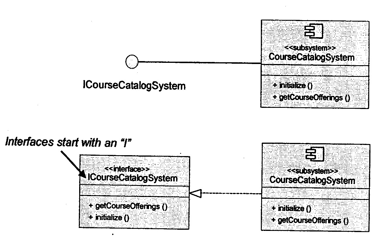
Interfaces are a natural evolution from the public classes of a package (described on the previous slide) to abstractions outside the subsystem. Interfaces are pulled out of the subsystem like a kind of antenna, through which the subsystem can receive signals. All classes inside the subsystem are then private and not accessible from the outside.
-
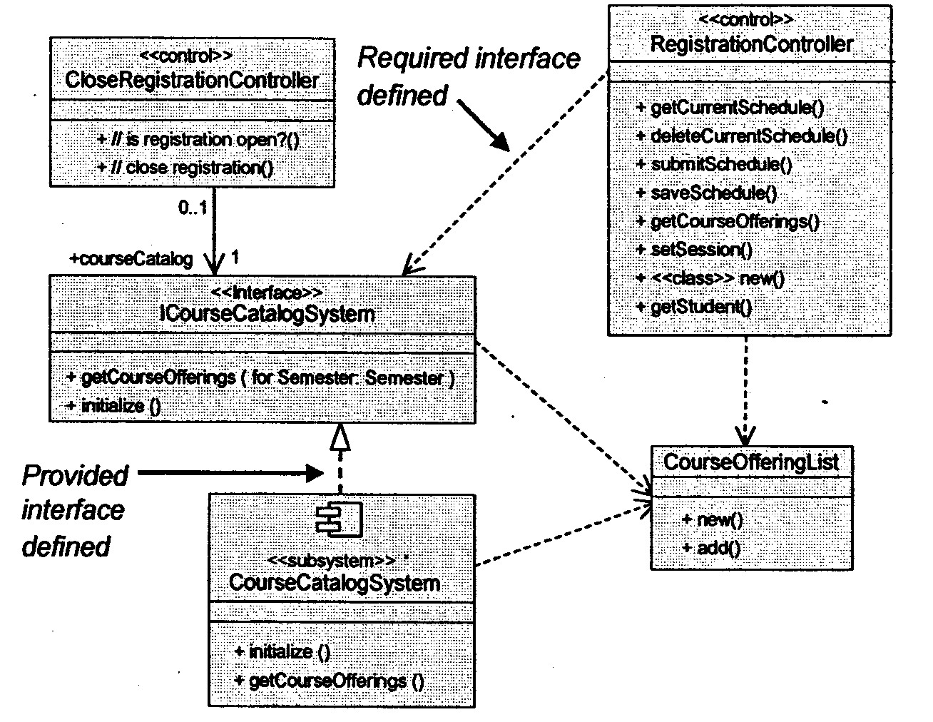
A subsystem encapsulates its implementation behind one (or more) interfaces. Interfaces isolate the rest of the architecture from the details of the implementation Operations defined for the interface are implemented by one or more elements contained within the subsystem.
-
An interface is a pure specification. Interfaces provide the "family of behavior" that a classifier that implements the interface must support. Interfaces are separate things that have separate life spans from the elements that realize them. This separation of interface and implementation exemplifies the OO concepts of modularity and encapsulation, as well as polymorphism.
-
Note: Interfaces are not abstract classes. Abstract classes allow you to provide default behavior for some or all of their methods. Interfaces provide no default behavior.
-
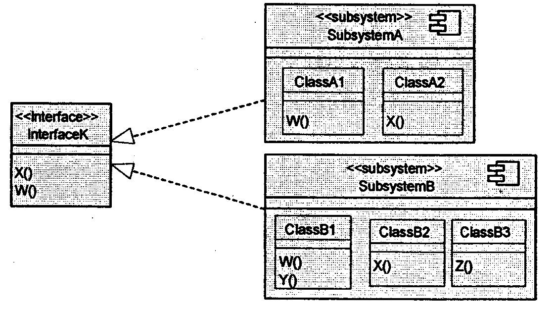
-
As mentioned earlier, and interface can be realized by one or more subsystems. Any two subsystems that realize the same interfaces can be substituted for one another. The benefit of this is that, unlike a package, the contents and internal behaviors of a subsystem can change with complete freedom, so long as the subsystem's interfaces remain constant.
Packages versus Subsystems:
-
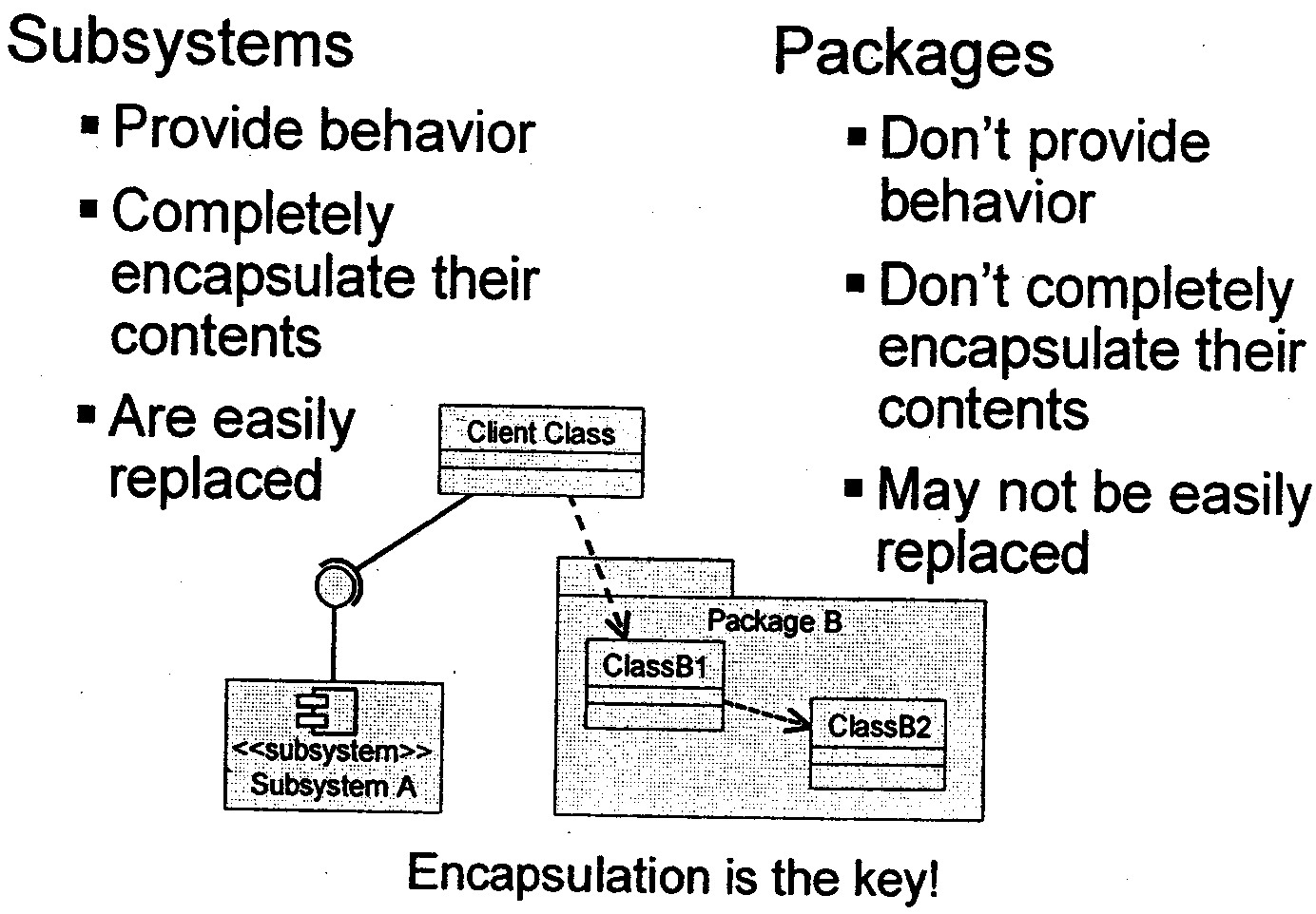
A subsystem provides interfaces by which the behavior it contains can be accessed. Packages provide no behavior; they are simply containers of things that have behavior. Packages help organize and control sets of classes that are needed in common, but which are not really subsystems. Package are just used for model organization and configuration management.
-
Subsystem completely encapsulate their contents, providing behavior only through their interfaces. Dependencies on a subsystem are on its interface(s), not on specific subsystem contents. With packages, dependencies are on specific elements within the package.
-
With subsystems, the contents and internal behaviors of a subsystem can change with complete freedom as long as the subsystem's interfaces remain constant. With packages, it is impossible to substitute packages for one another unless they have the same public classes. The public classes and their public operations get frozen by the dependencies that external classes have on them. Thus, the designer is not free to eliminate these classes or change their behaviors if a better idea presents itself.
-
Note: Even when using packages, it is important that you hide the implementation from elements external to the package. All dependencies on a package should be on the public classes of the package. Public classes can be considered the interface of the package and should be managed as such (stabilized early).
-
Subsystem Usage:
-
Subsystems can be used to partition the system into parts that can be independently:
-
ordered, configured, or delivered
-
developed, as long as the interfaces remain unchanged
-
deployed across a set of distributed computational nodes
-
changed without breaking other parts of the systems
-
-
Subsystems can also be used to:
-
partition the system into units which can provide restricted security over key resources
-
represent existing products or external systems in the design (e.g. components)
-
-
Subsystems can be used to represent components from the Implementation Model in the Design Model.
-
Subsystem raise the level of abstraction
Identifying subsystems Hints:
-
Look at object collaborations
-
If the classes in a collaboration interact only with each other to produce a well-defined set of results, then encapsulate them within a subsystem.
-
-
Look for optionality
-
If collaborations model optional behavior, or features that may be removed, upgraded, or replaced with alternatives, then encapsulate them within a subsystem
-
-
Look to the user interface of the system
-
Create "horizontal" subsystems (boundary classes and related entity classes in separate subsystem) or "vertical" subsystems (related boundary and entity classes in the same subsystem), depending on the coupling of the user interface and entity classes.
-
-
Look to the actors
-
Partition functionality used by two different actors, since each actor can independently change requirements
-
-
Look for coupling and cohesion between classes
-
Organize highly coupled classes into subsystems, separating along the lines of weak coupling.
-
-
Look at substitution
-
Represent different service levels for a particular capability (for example, high, medium, and low availability) as a separate subsystem, that realizes the same interfaces.
-
-
Look at distribution
-
If particular functionality must reside on a particular node, ensure that the subsystem functionality maps onto a single node.
-
-
Look at volatility
-
You will want to encapsulate those chunks of your system that you expect to change.
-
Candidate Subsystems:
-
Examples of analysis classes that may evolve into subsystems include:
-
Classes providing complex services and/or utilities. For example:
-
Credit or risk evaluation engines in financial applications
-
Rule-based evaluation engines in financial applications
-
Security authorization services in most applications
-
-
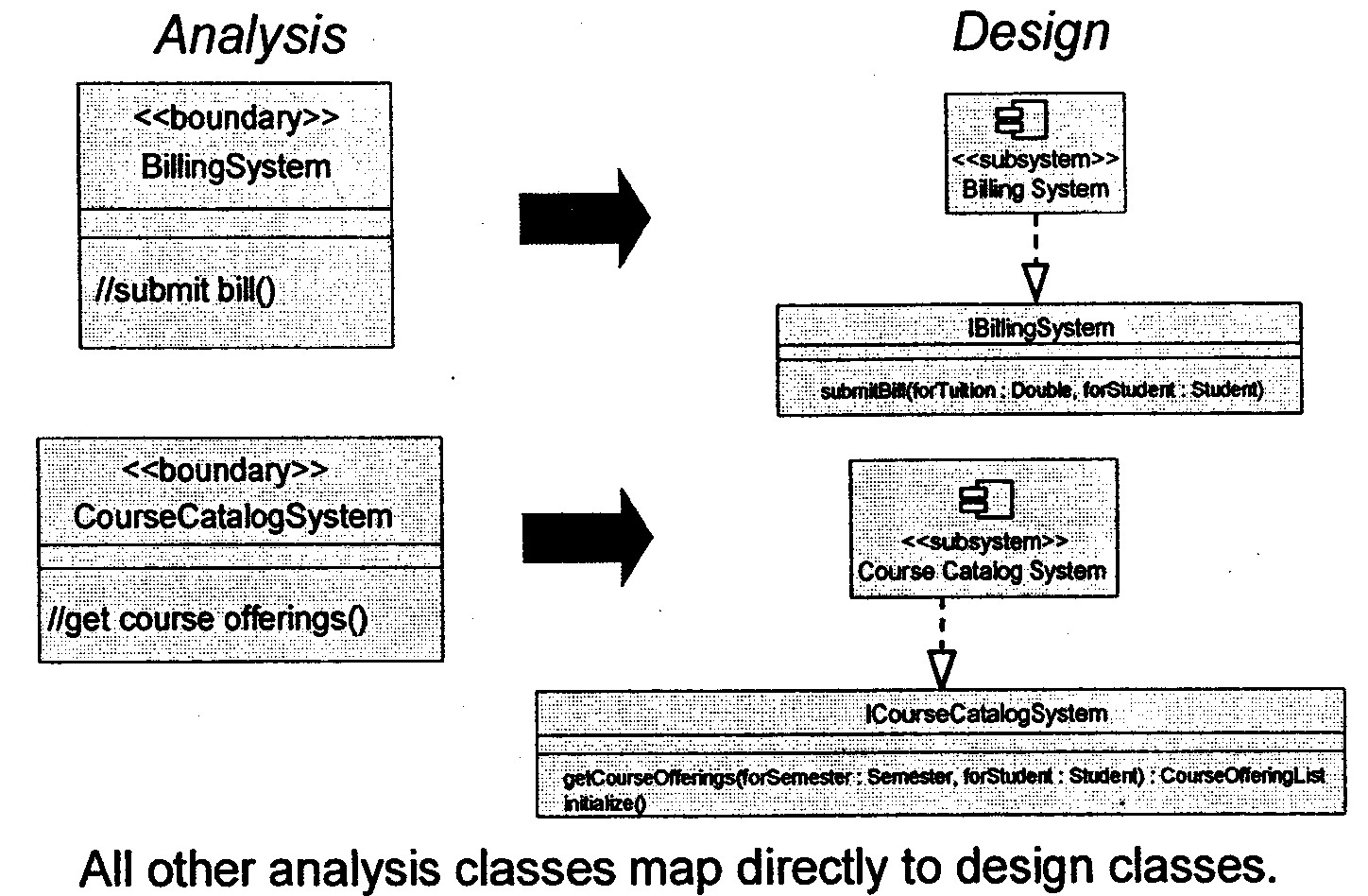
Boundary classes, both for user interfaces and external system interfaces. If the interface(s) are simple and well-defined, a single class class may be sufficient. Often, however, these interfaces are too complex to be represented using a single class. They often require complex collaborations of many classes. Moreover, these interface may be reusable across applications. As a result, a subsystem more appropriately models these interfaces in many cases.
-
-
Examples of products the system uses that you can represent by a subsystem include:
-
Communication software (middle-ware, COM/CORBA support)
-
Database access support (RDBMS mapping support)
-
Types and data structures (stacks, lists, queues)
-
Common utilities (math libraries)
-
Application-specific products (billing system, scheduler)
-
Identifying Subsystems:
-
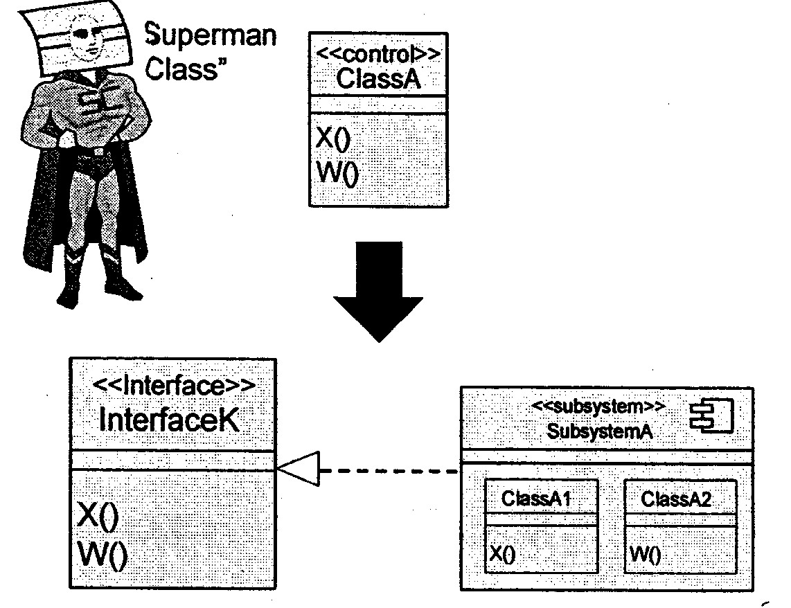
When the analysis class is complex, such that it appears to embody behaviors that cannot be the responsibility of a single class acting alone, or the responsibilities may need to be reused, the analysis class should be refined into a subsystem. This a decision based largely on conjecture guided by experience. The actual representation may take a few iterations to stabilize.
-
The decision to make something a subsystem is often driven by the knowledge and experience of the architect. Since it tends to have a strong effect on the partitioning of the solution space, the decision needs to be made in the context of the whole model. It is the result of more detailed design knowledge, as well as the imposition of constraints imposed by the implementation environment.
-
When an analysis class is evolved into a subsystem, the responsibilities that were allocated to the "superman" analysis class are then allocated to the subsystem and an associated interface (that is, they are used to define the interface operations). The details of how that subsystem actually implements the responsibilities (that is, the interface operations) is deferred until Subsystem Design.