Rose Modeling Basics
Last updated: April. 11, 2006
Objectives: After completing this module, you will be able to
Select the views and diagrams various stakeholders will need, based on their project responsibilities.
Quickly find the Rose interface features and functions and setup information needed to create and modify your models and diagrams.
Models, Views, and Diagrams in Rational Rose:
A model is a simplification of reality or the blueprint of the system.
Models are constructed using views to depict different perspectives and diagrams to depict a system's building blocks.
An architectural view can be defined as a simplified description (an abstraction) of a system from a particular perspective or vantage point, covering particular concerns, and omitting entities that are not relevant to this perspective. Views are "slices" of models. Working together, they are the model or blueprint.
Diagrams are the means by which you visualize collections of these abstractions (or views).
When you construct your models, you can choose to create only those views significant for that iteration of development and of value to the project stakeholders.
Stakeholder:
Software Architect: is responsible for development of the entire project and needs to understand all aspects of the system.
System Analyst: identifies functionality (actors and use cases) of the system based on user requirements.
Designer: builds the system to meet the specifications identified by the analyst, generates the software.
End-user ensures that the design of the system meets his/her requirements.
Views:
In Rose, you can create the following views:
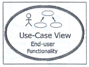
Use-Case View
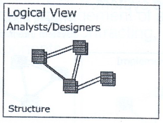
Logical View
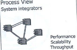
Process View
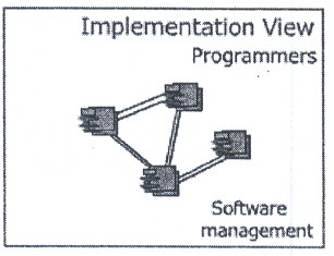
Component View (Implementation View)
Deployment View
Use-Case View
Includes the use-case model, which represents the system's intended functions and environment as seen by its users.
Serves as a contract between customer and developer.
Is essential to analysis and design and test activities.
Includes use-case diagrams, use-case flow of events, and supplemental documentation. It can also include activity diagrams.
Is the heart of the other views because it represents the required behavior of the system.
Logical View:
Supports the functional requirements of the system, meaning the services the system should provide its users.
Includes use-case realizations, class and interaction diagrams. It can also include statechart and activity diagrams.
Process View:
Includes the threads and processes that form the system's concurrency and synchronization mechanisms.
Addresses the performance, scalability, and throughput of the system.
Is not necessary for a single processing environment.
Component View (Implementation View):
In Rose, the Implementation View is called the component View.
Describes the organization of static software modules (source code, data files, components, executables, and so on) in terms of packaging and layering and configuration management.
Addresses issues of ease of development, management of software assets, reuse, sub-contracting, and off-shelf components.
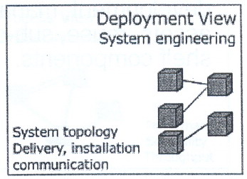
Deployment View:
Is used for distributed systems only.
Shows how the various executables and other runtime components are mapped to the underlying platforms or computing nodes.
Addresses issues like deployment, installation, and performance.
Shows one deployment diagram.
Diagrams are the means by which to view the system's building blocks, classes, interfaces, collaborations, components, nodes, dependencies, generalizations, and associations.
Rational Rose Interface:
The Rose interface includes the following:
Browser
Diagram window
Diagram toolbar
Documentation window
Log window
Options window
The Browser:
Is used to textually view and navigate what you've modeled.
Displays the elements that you've modeled. If an element doesn't appear in the browser, it is not a part of your modeled system.
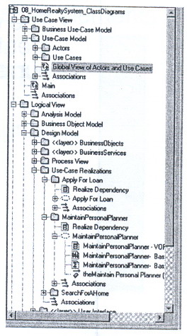
Diagram Window:
Allows you to create and update graphical views of the current model.
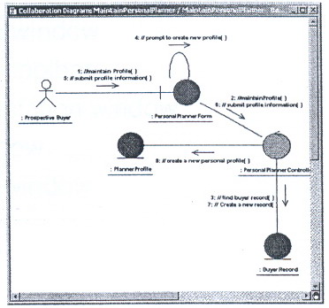
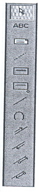
Diagram toolbar:
The diagram toolbar includes the elements to build a diagram.
Each diagram's toolbar is unique to that diagram.
It is active only when the diagram is displayed.
Documentation Window:
Is used to create, view, or modify text that explains a selected item within a diagram.
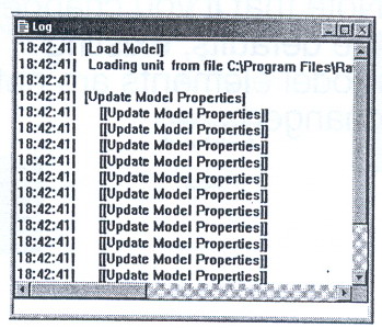
Log Window:
The log window reports progress, results, and errors. For example, code generation commands post progress and error messages to this window.
There is only one log window.
Messages are posted whether the log window is displayed or not.
To display the log window: View -> Log
To clear the contents of the log window: File -> Clear Log
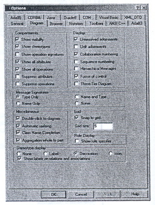
options Windows:
Allows you to set your defaults.
Applies new settings to future additions made to a diagram. Changes will NOT be applied to existing elements. In other words, Rose does not apply the new setting globally.
For specific topic information: click? -> click the field
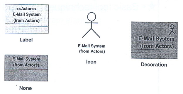
Select how you want stereotypes to appear on your diagrams: Options -> Diagram -> Stereotype Display
Basic Tool Techniques:
There are two basic tool techniques we will discuss before you begin the labs. They are:
Deleting diagram elements
Adding diagram elements
Deleting Diagram Elements:
What happens when you delete an element from the browser? Rose does the following:
Removes the selected element from the model.
Removes all icons representing the element from all diagrams on which they appear.
Deletes the specification for the elements.
What happens when you delete an element from a diagram?
Rose removes the selection from the current diagram, BUT DOES NOT CHANGE THE MODEL unless the icon is unnamed and appears only once in the current diagram and in no other diagrams.
Ways to delete an element from the browser?
Click the element in the diagram -> press Ctrl-D
Right-click the element in browser -> Delete
Click the element in the browser or diagram -> Edit -> Delete from Model
Ways to delete an element from a diagram:
Click the element in the diagram -> press Delete
Click the element in the diagram -> Edit -> Delete
Adding Diagram Elements:
From the Diagram Toolbar: click the element -> click in the diagram window
If this is a new elements, Rose automatically adds the element to the browser.
What if the element is missing in the toolbar? Right-click in the toolbar -> Customize -> Add the needed elements from the Customize Toolbar window
From the Browser: Click the element, and then drag it from the browser to the diagram window.
The browser displays elements that are already in included in a model's diagrams.
What if the element does not appear in the browser? Right-click the view for the diagram -> New -> Add the element.
Practice Basic Tool Skills:
Copy all files from the CD to your hard drive: D:\s???????\
Add the Creates an Associations Relationship icon to a diagram:
Open Lab2-1.mdl
Expend Use Case View -> Expand Use-Case Model
Open the Global View of Actors and Use Cases Diagram
Add the icon.
delete the Maintain Personal Planner use case from the browser:
Expand Use Cases -> Expand Maintain Personal planner.
Delete the Maintain Personal Planner use case in the browser.
Notice what happens in the Global View of Actors and Use Cases diagram.
Delete the Find Realtor use case from the use-case diagram:
Is it deleted from the browser?
Add a use case from the diagram toolbar:
Is the use case added to the browser?
Add a new use case under the Search for a Home package in the browser:
Is the use case added to the diagram?
No. You can drag it to the diagram from the browser once it's created.
File -> Save