Last updated: May. 17, 2006
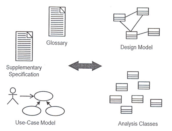
For each use-case flow of events:
Identify analysis classes
Allocate use-case responsibilities to analysis classes
Model analysis class interactions in Interaction diagrams
In addition to the identified analysis classes, the Interaction diagram should show interactions of the system with its actors. The interactions should begin with an actor, since an actor always invokes the use case. If you have several actor instances in the same diagram, try keeping them in the periphery of that diagram.
Interactions between actors should not be modeled. By definition, actors are external, and are out of scope of the system being developed. Thus, you do not include interactions between actors in your system model. If you need to model interactions between entities that are external to the system that you are developing (for example, the interactions between a customer and an order agent for an order-processing system), those interactions are best included in a Business Model that drives the System Model.
Guidelines: Allocating Responsibilities to Classes
Use analysis class stereotypes as a guide:
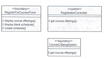
Boundary Classes: Behavior that involves communication with an actor
Entity Classes: Behavior that involves the data encapsulated within the abstraction
Control Classes: Behavior specific to a use case or part of a very important flow of events
Who has the data needed to perform the responsibility?
If one class has the data, put the responsibility with the data:
If multiple classes have the data:
put the responsibility with one class and add a relationship to the other
Create a new class, put the responsibility in the new class, and add relationships to classes needed to perform the responsibility
Put the responsibility in the control class, and add relationships to classes needed to perform the responsibility
Be careful when adding relationships ¡Ð all relationships should be consistent with the abstractions they connect. Do not just add relationships to support the implementation without considering the overall effect on the model.
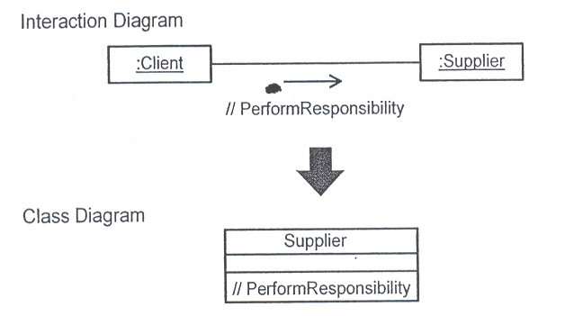
When a new behavior is identified, check to see if there is an existing class that has similar responsibilities, reusing classes where possible, you should create new classes only when you are sure that there is no existing object that can perform the behavior.
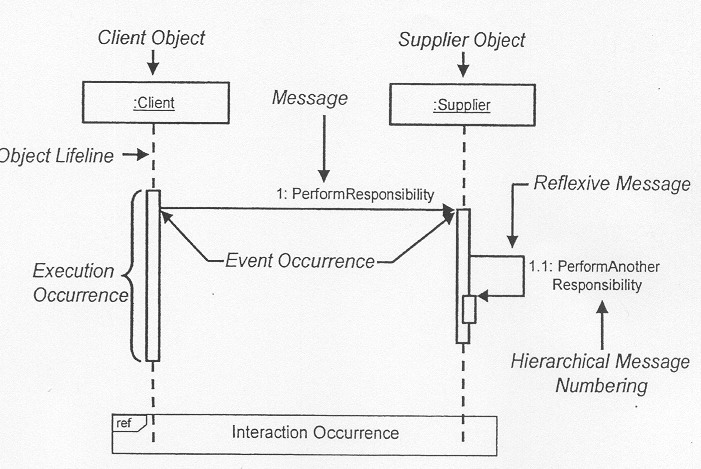
The Anatomy of Sequence Diagrams:
A sequence diagram describes a pattern of interaction among object, arranged in a chronological order. It shows the objects participating in the interaction and the message they send.
Hierarchical numbering bases all message on a dependent message.
Notes: describe the flow of events textually.
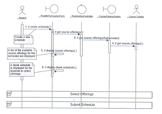
Example: Sequence Diagram
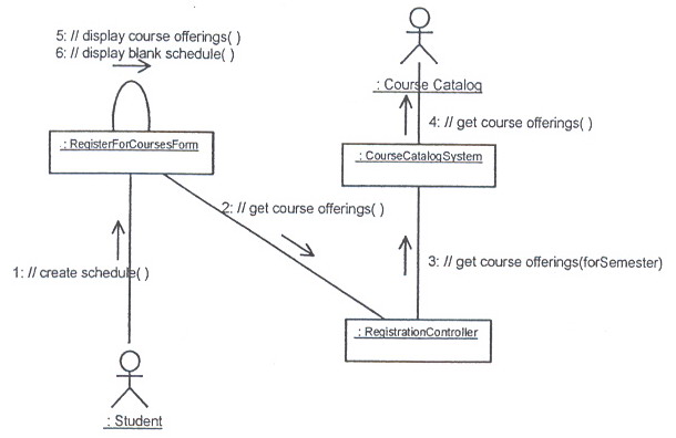
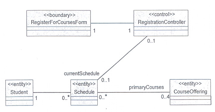
The object interactions to support the Create a Schedule sub-flow of the Register for Courses use case.
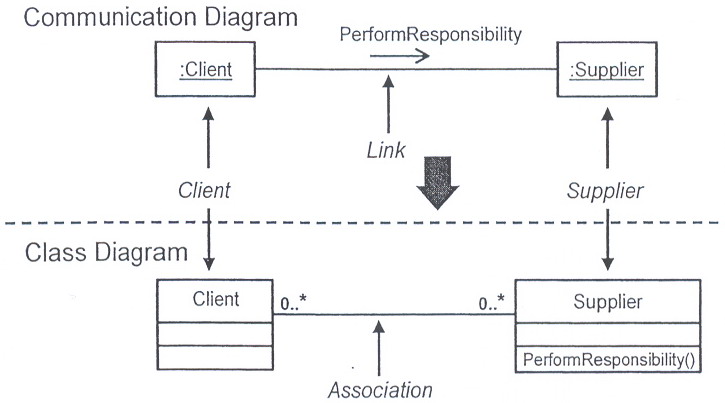
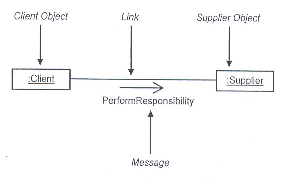
The Anatomy of Communication Diagrams:
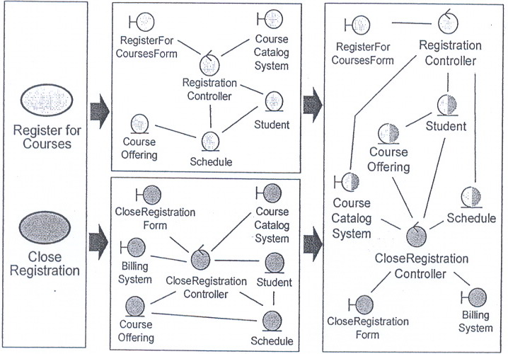
A communication diagram describes a pattern of interaction among objects. It shows the objects participating in the interaction by their links to each other and the messages that they send to each other.
An object is represented in one of three ways:
Objectname: Classname
ObjectName
:ClassName
The arrow may also be labeled with a sequence number to show the sequence of the message in the overall interaction.
A message can be unassigned, meaning that its name is a temporary string that describes the overall meaning of the message. You can later assign the message by specifying the operation of the message's destination object. The specified operation will then replace the name of the message.
Example: Communication Diagram
Model most of the flow of events to make sure that all requirements on the operations of the participating classes are identified.
Start with describing the basic flow, which is the most common or most important flow of events.
Then describe variants such as exceptional flows.
Examples of exceptional flows: Error handling, Time-out handling.
Examples of optional flows:
The actor decides-from a number of options ¡Ð what the system is to do next.
The subsequent flow of events depends on the value of stored attributes or relationships.
The subsequent flow of events depends on the type of data to be processed.
You do not have to describe all the flow of events, as long as you employ and exemplify all operations of the participating objects. Very trivial flows can be omitted, such as those that concern only one object.
You can use either Communication or Sequence diagrams.
Communication Diagrams V.S. Sequence Diagrams:
Communication Diagrams |
Sequence Diagrams |
¡DShow relationships in addition to interactions ¡DBetter for visualizing patterns of collaboration ¡DBetter for visualizing all of the effects on a given object ¡DEasier to use for brainstorming sessions |
¡DShow the explicit sequencer of messages ¡DBetter for visualizing overall flow ¡DBetter for real-time specifications and for complex scenarios |
¡@
Describe Responsibilities:
A class and its objects often participate in several Use-Case Realizations. It is important to coordinate all the requirements on a class and its objects that different Use-Case Realizations may have
The ultimate objective of these class-focused activities is to document what the class knows and what the class does.
What are responsibilities?
A responsibility is a statement of something an object can be asked to provide.
Responsibilities evolve into one (or more) operations on classes in design; they can be characterized as:
The actions that the object can perform
The knowledge that the object maintains and provides to other objects
How do I find Them?
Responsibilities are derived from messages on Interaction diagrams.
Other responsibilities will derive from nonfunctional requirements.
When you create a new responsibility, check the nonfunctional requirements to see if there are related requirements that apply. Either augment the description of the responsibility, or create a new responsibility to reflect this.
Analysis class responsibilities can be documented in one of two ways:
As "analysis" operations: These "analysis" operations WILL PROBABLY change/evolve in design.
Textually: In this approach, the analysis class responsibilities are documented in the description of the analysis classes.
Example: View of Participating Classes (VOPC) Class Diagram
The VOPC class diagram contains the classes whose instances participate in the Use-Case Realizations interaction diagrams, as well as the relationships required to support the interactions.
Maintaining Consistency: What to Look for
Examine classes to ensure they have consistent responsibilities. When a class's responsibilities are disjoint, split the object into two or more classes. Update the Interaction diagrams accordingly.
Examine classes to ensure that there are not two classes with similar responsibilities. When classes have similar responsibilities, combine them and update the Interaction diagrams accordingly.
Be prepared to challenge and justify the existence of all classes.
Take the time to set the diagrams right, but do not get hungup trying to optimize the class interactions.
In order of criticality:
Redundant responsibilities across classes
Disjoint responsibilities within classes
Class with one responsibility
Class with no responsibilities
Better distribution of behavior
Class that interacts with many other classes
Describe Attributes and Associations:
The purpose of Describe Attributes and Operations is to:
Identify the other classes on which the analysis class depends.
Define the events in other analysis classes that the class must know about.
Define the information that the analysis class is responsible for maintaining.
Review: What Is an Attribute?
Attributes are used to store information. They are atomic things with no responsibilities.
During Analysis, the attribute types should be from the domain, and not adapted to the programming language in use.
Finding Attributes:
Attributes are domain-dependent.
Attributes are Properties/Characteristics of identified classes.
Attributes are Information retained by identified classes
Attributes are "Nouns" that did not become classes
Information whose value is the important thing
Information that is uniquely "owned" by an object
Information that has no behavior
Remember, the process is use-case-driven. Thus, all discovered attributes should support at least one use case. For this reason, the attributes that are discovered are affected by what functionality/domain is being modeled.
Finding Relationships:
To find relationships, start studying the links in the Communication diagrams.
Focus only on associations needed to realize the use cases; do not add associations you think "might" exist unless they are required based on the Interaction diagrams.
Remember to give the associations role names and multiplicities.
Write a brief description of the association to indicate how the association is used, or what relationships the association represents.
Example: The relationship from Student to Schedule is modeled as an aggregation, because a Schedule is inherently tied to a particular Student.
Association or Aggregation?
The use of aggregation versus association is dependent on the application you are developing. For example, if you are modeling a car dealership, the relationship between a car and the doors might be modeled as aggregation, because the car always comes with doors, and doors are never sold separately. However, if you are modeling a car parts store, you might model the relationship as an association, as the car (the body) might be independent of the doors.
Choosing aggregation is only done to help clarify; it is not something that is crucial to the success of the modeling effort.
When in doubt, an association is more appropriate.
What are Roles?
The "face" that a class plays in the association.
The use of association names and role names is mutually exclusive: one would not use both an association name and a role name.
Multiplicity answers two questions:
Is the association mandatory or optional?
What is the minimum and maximum number of instances that can be linked to one instance?
Many times you do not know what the maximum number of instances may be, and you will use the "*" to specify that this number is unknown.
Example: Multiple Associations
There can be multiple associations between the same two classes, but they should represent distinct relationships, and DIFFERENT ROLES; they should not be just for invoking different operations.
If there is more than one association between two classes then they MUST be named.
It is unusual to find more than one association between the same two classes. Occurrences of multiple associations should be carefully examined.
Example: VOPC: Finding Relationships:
From RegisterForCoursesForm to RegistrationController: There is one controller for each Schedule being created (for example, each Student registration session)
From RegistrationController to Schedule: A RegistrationController deals with one Schedule at a time (the current Schedule for the Student registering for courses). Note the use of the "current Schedule" role name. Note: Many RegisterForCoursesForms can be active at one time (for different session/students), each with their own RegistrationController.
From Schedule to CourseOffering: Each Schedule may have up to four primary Course Offerings and up to two alternate Course Offerings. A particular Course Offering may appear on many Schedules as either a primary or an alternate.
From Student to Schedule: A Student may have many schedules or none. A Schedule is only associated with a single Student and dose not exist without a Student to be associated to.
Qualify Analysis Mechanisms:
The purpose of the Qualify Analysis Mechanism step is to:
Identify analysis mechanisms (if any) used by the class.
Provide additional information about how the class applies the analysis mechanism.
For each such mechanism, qualify as many characteristics as possible, giving ranges where appropriate, or when there is still much uncertainty.
The analysis mechanism characteristics should be documented with the class.
Describing Analysis Mechanisms:
Collect all analysis mechanisms in a list
Draw a map of the client classes to the analysis mechanisms
Identify characteristics of the analysis mechanisms
Example: Analysis class to analysis mechanism map
Analysis Class |
Analysis Mechanism (s) |
Student |
Persistency, Security |
Schedule |
Persistency, Security |
CourseOffering |
Persistency, Legacy Interface |
Course |
Persistency, Legacy Interface |
RegistrationController |
Distribution |
Example: Analysis mechanism characteristics
Persistency for Schedule class:
Granularity: 1 to 10 Kbytes per product
Volume: up to 2,000 schedules
Access frequency
Create: 500 per day
Read: 2,000 access per hour
Update: 1,000 per day
Delete: 50 per day
Other characteristics
Unify Analysis Classes:
The purpose of Unify Analysis Classes is to ensure that each analysis class represents a single well-defined concept, with non-overlapping responsibilities
Before the Design work can be done, the analysis classes need to be filtered to ensure that a minimum number of new concepts have been created.
A class can participate in any number of use cases. It is therefore important to examine each class for consistency across the whole system.
Different use cases will contribute to the same classes.
Evaluate Your Results:
It is very important that you evaluate your results at the conclusion of the Use-Case Analysis.
Be sure to:
Verify that the analysis classes meet the functional requirements made on the system.
Verify that the analysis classes and their relationships are consistent with the collaborations they support.
Checkpoints:
Analysis classes:
Are the classes reasonable?
Does the name of each class clearly reflect the role it plays?
Does the class represent a single well-defined abstraction?
Are all attributes and responsibilities functionally coupled?
Does the class offer the required behavior?
Are all specific requirements on the class addressed?
Use-Case Realizations:
Have all the main and/or sub-flows been handled, including exceptional cases?
Have all the required objects been found?
Has all behavior been unambiguously distributed to the participating objects?
Has behavior been distributed to the right objects?
Where there are several Interaction diagrams, are their relationships clear and consistent?