Module 7: Distance Vector Routing Protocols
7.1 Distance Vector Routing
7.1.1 Distance vector routing updates
Routing table updates occur periodically or when the topology in a distance vector protocol network changes.
It is important for a routing protocol to update the routing tables efficiently.
7.1.2 Distance vector routing loop issues
Routing loops can occur when inconsistent routing tables are not updated due to slow convergence in a changing network.
An example is as follows:
7.1.3 Defining a maximum count
The invalid updates of Network 1 will continue to loop until some other process stops the looping. This condition, which is called count to infinity, loops packets around the network in spite of the fact that the destination network, which is Network 1, is down.
The distance vector metric of hop count increases each time the packet passes through another router.
To avoid this prolonged problem, distance vector protocols define infinity as a specific maximum number. This number refers to a routing metric, which may simply be the hop count.
With this approach, the routing protocol permits the routing loop to continue until the metric exceeds its maximum allowed value.
The graphic shows the metric value as 16 hops. This exceeds the distance vector default maximum of 15 hops so the packet is discarded by the router. When the metric value exceeds the maximum value, Network 1 is considered unreachable.
7.1.4 Elimination routing loops through split-horizon
Some routing loops occur when incorrect information that is sent back to a router contradicts the correct information that the router originally distributed.
An example is as follows:
7.1.5 Route poisoning
Route poisoning is used by various distance vector protocols to overcome large routing loops and offer detailed information when a subnet or network is not accessible. To accomplish this, the hop count is usually set to one more than the maximum.
One way to avoid inconsistent updates is route poisoning.
When Network 5 goes down, Router E will set a distance of 16 for Network 5 to poison the route. This indicates that the network is unreachable.
When the route is poisoned, Router C is not affected by incorrect updates about the route to Network 5.
After Router C receives a route poisoning from Router E, it sends an update, which is called a poison reverse, back to Router E. This makes sure all routers on the segment have received the poisoned route information.
When route poisoning is used with triggered updates it will speed up convergence time because neighboring routers do not have to wait 30 seconds before they advertise the poisoned route.
Route poisoning causes a routing protocol to advertise infinite-metric routes for a failed route.
Route poisoning does not break split horizon rules.
7.1.6 Avoiding routing loops with triggered updates
New routing tables are sent to neighbor routers on a regular basis. For example, RIP updates occur every 30 seconds.
A triggered update is sent immediately in response to some change in the routing table. The router that detects a topology change immediately sends an update message to adjacent routers.
Triggered updates, used in conjunction with route poisoning, ensure that all routers know of failed routes before any holddown timers can expire.
Triggered updates do not wait for update timers to expire. They are sent when routing information has changed.
Example:
Router C issues a triggered update, which announces that network 10.4.0.0 is unreachable. Upon receipt of this information, Router B announces through interface S0/1 that network 10.4.0.0 is down. In turn, Router A sends an update out interface Fa0/0.
7.1.7 Preventing routing loops with holddown timers
This page will explain how holddown timers can be used to avoid a count to infinity problem:
7.2 RIP
7.2.1 RIP routing process
The modern open standard version of RIP, which is sometimes referred to as IP RIP, is formally detailed in two separate documents. The first is known as Request for Comments (RFC) 1058 and the other as Internet Standard (STD) 56.
RIP has evolved over the years from a Classful Routing Protocol, RIP Version 1 (RIP v1), to a Classless Routing Protocol, RIP Version 2 (RIP v2). RIP v2 enhancements include the following:
To prevent indefinite routing loops, RIP implements a limit on the number of hops allowed in a path from a source to a destination. The maximum number of hops in a path is 15.
When a router receives a routing update that contains a new or changed entry, the metric value is increased by 1 to account for itself as a hop in the path. If this causes the metric to be higher than 15, the network destination is considered unreachable.
RIP implements split horizon and holddown mechanisms to prevent the propagation of incorrect routing information.
7.2.2 Configuring RIP
The router rip command enables RIP as the routing protocol.
The network command is then used to tell the router on which interfaces to run RIP. The routing process associates specific interfaces with the network addresses and begins to send and receive RIP updates on these interfaces.
RIP routers maintain only the best route to a destination but can maintain multiple equal-cost paths to the destination.
Most routing protocols use a combination of time-driven and event-driven updates. RIP is time-driven, but the Cisco implementation of RIP sends triggered updates whenever a change is detected.
Topology changes also trigger immediate updates in IGRP routers, regardless of the update timer.
Example to configure router BHM:
The Cisco router interfaces that are connected to networks 10.0.0.0 and 192.168.13.0 send and receive RIP updates. These routing updates allow the router to learn the network topology from a directly connected router that also runs RIP.
RIP must be enabled and the networks must be specified. All other tasks are optional. These optional tasks include the following:
To enable RIP, use the following commands in global configuration mode:
Lab Exercise: Configuring RIP
This lab is to setup an IP addressing scheme using class B networks and configure the RIP dynamic routing protocol on routers.
7.2.3 Using the ip classless command
This page will explain what the ip classless command is and how it is used.
Sometimes a router receives packets destined for an unknown subnet of a network that has directly connected subnets. Use the ip classless global configuration command to instruct the Cisco IOS software to forward these packets to the best supernet route.
A supernet route is a route that covers a greater range of subnets with a single entry.
For example, if an enterprise uses the entire subnet 10.10.0.0 /16, then a supernet route for 10.10.10.0 /24 would be 10.10.0.0 /16.
The ip classless command is enabled by default in Cisco IOS Software Release 11.3 and later. To disable this feature, use the no form of this command.
When this feature is disabled any packets received that are destined for a subnet that falls within the subnetwork addressing scheme of the router will be discarded.
IP classless only affects the operation of the forwarding processes in IOS. IP classless does not affect the way the routing table is built.
This is the essence of classful routing. If one part of a major network is known, but the subnet toward which the packet is destined within that major network is unknown, the packet is dropped.
Question:
The most confusing aspect of this rule is that the router only uses the default route if the major network destination does not exist in the routing table.
A router by default assumes that all subnets of a directly connected network should be present in the routing table.
If a packet is received with an unknown destination address within an unknown subnet of a directly attached network, the router assumes that the subnet does not exist. So the router will drop the packet even if there is a default route.
Solution:
To resolve this problem, configure ip classless on the router. This allows the router to ignore the classful boundaries of the networks in its routing table and simply route to the default route.
7.2.4 Common RIP configuration issues
To reduce routing loops and counting to infinity, RIP uses the following techniques:
Maximum hop count:
RIP permits a maximum hop count of 15.
This maximum hop count greatly restricts the use of RIP in large internetworks but prevents counts to infinity and endless network routing loops.
Split horizon :
The split horizon rule is based on the theory that it is not useful to send information about a route back in the direction from which it came. In some network configurations, it may be necessary to disable split horizon.
The following command is used to disable split horizon:
GAD(config-if)#no ip split-horizon
Holddown timers:
To help prevent counting to infinity but also increase convergence time.
The default holddown for RIP is 180 seconds.
Ideally, the timer should be set just longer than the longest possible update time for the internetwork.
In the example in Figure, the loop consists of four routers. If each router has an update time of 30 seconds, the longest loop would be 120 seconds. Therefore, the holddown timer should be set to slightly more than 120 seconds.
Use the following command to change the holddown timer as well as the update, invalid, and flush timers:
Router(config-router)#timers basicupdate invalid holddown flush [sleeptime ]
Update interval:
The default RIP update interval in Cisco IOS is 30 seconds. This can be configured for longer intervals to conserve bandwidth, or for shorter intervals to decrease convergence time.
disable routing updates :
A network administrator can use the passive-interface command to disable routing updates on specified interfaces.
In a non-broadcast network:
Because RIP is a broadcast protocol, the network administrator may have to configure RIP to exchange routing information in a non-broadcast network such as Frame Relay. In this type of network, RIP must be informed of neighbor RIP routers. To do this use the neighbor command displayed in Figure 4.
Version:
By default, the Cisco IOS software receives RIP Version 1 and Version 2 packets, but sends only Version 1 packets.
To configure the router to send and receive packets from only one version, use the commands in Figure 5.
To control how packets received from an interface are processed, use the commands in Figure 6.
7.2.5 Verifying RIP configuration
The show ip protocols command shows which routing protocols carry IP traffic on the router. This output can be used to verify most if not all of the RIP configuration. Some of the most common configuration items to verify are as follows:
The show ip route command can be used to verify that routes received by RIP neighbors are installed in the routing table. Examine the output of the command and look for RIP routes signified by "R".
Remember that the network will take some time to converge so the routes may not appear immediately.
Additional commands to check RIP configuration are as follows:
e-Lab Activity: Verifying RIP Configuration
This lab is to use IOS show commands to verify the operation of a router running RIP.
7.2.6 Troubleshooting RIP update issues
The debug ip rip command displays RIP routing updates as they are sent and received.
The example in Figure 1 shows the output from the debug ip rip command after a router receives a RIP update.
After the router receives and processes the update, it sends the updated information out its two RIP interfaces.
The output shows the router uses RIP v1 and broadcasts the update with the broadcast address 255.255.255.255.
The number in parenthesis represents the source address encapsulated into the IP header of the RIP update.
Problems such as discontiguous subnetworks or duplicate networks can be diagnosed with this debug ip rip command. A symptom of these issues would be a router that advertises a route with a metric that is less than the metric it received for that network.
The following commands can also be used to troubleshoot RIP:
Lab Exercise: Troubleshooting RIP
This lab is to set up an IP addressing scheme using class B networks.
7.2.7 Preventing routing updates through an interface
Route filters have no effect on link-state advertisements or the link-state database. For this reason, the information on this page only applies to distance vector IP routing protocols such as RIP and IGRP.
The passive-interface command prevents the transmission of routing updates through a router interface.
In Figure 1, Router E uses the passive-interface command to prevent routing updates from being sent.
For RIP and IGRP, the passive-interface command stops the router from sending updates to a particular neighbor, but the router continues to listen and use routing updates from that neighbor.
7.2.8 Load balancing with RIP
Load balancing is a concept that allows a router to take advantage of multiple best paths to a given destination. These paths are either statically defined by a network administrator or calculated by a dynamic routing protocol such as RIP.
RIP is capable of load balancing over as many as six equal-cost paths. The default is four paths.
RIP performs what is referred to as “round robin” load balancing. This means that RIP takes turns forwarding packets over the parallel paths.
Figure 1 shows an example of RIP routes with four equal cost paths.
The router will start with an interface pointer to the interface connected to Router 1. Then the interface pointer cycles through the interfaces and routes in a deterministic fashion such as 1-2-3-4-1-2-3-4-1 and so on.
Since the metric for RIP is hop count, the speed of the links is not considered. Therefore, the 56-Kbps path will be given the same preference as the 155-Mbps path.
The show ip route command can be used to find equal cost routes.
For example, Figure 2 is a display of the output show ip route to a particular subnet with multiple routes.
Notice there are two routing descriptor blocks. Each block is one route. There is also an asterisk (*) next to one of the block entries. This corresponds to the active route that is used for new traffic.
7.2.9 Load balancing across multiple paths
When a router learns multiple routes to a specific network, the route with the lowest administrative distance is installed in the routing table.
Sometimes the router must select a route from among many, learned through the same routing process with the same administrative distance. In this case, the router chooses the path with the lowest cost or metric to the destination.
Each routing process calculates its cost differently and the costs may need to be manually configured in order to achieve load balancing.
If the router receives and installs multiple paths with the same administrative distance and cost to a destination, load-balancing can occur.
Cisco IOS imposes a limit of up to six equal cost routes in a routing table.
EIGRP allows up to four equal cost routes.
By default, most IP routing protocols install a maximum of four parallel routes in a routing table. Static routes always install six routes.
The exception is BGP, which by default allows only one path to a destination.
The range of maximum paths is one to six paths. To change the maximum number of parallel paths allowed, use the following command in router configuration mode:
Router(config-router)#maximum-paths [number ]
IGRP can load balance up to six unequal links. IGRP uses bandwidth to determine how to load balance.
RIP networks must have the same hop count to load balance,
In Figure 2, there are three ways to reach Network X:
Router E chooses the second path, E to C to A with a metric of 20, since it is a lower cost than 30 and 45.
Cisco IOS supports two methods of load balancing for IP packets. These are per-packet and per-destination load balancing.
Per-packet:
If process switching is enabled, the router will alternate paths on a per-packet basis.
Per-destination:
If fast switching is enabled, only one alternate route will be cached for the destination address. All packets that are bound for a specific host will take the same path. Packets bound for a different host on the same network may use an alternate route.
By default the router uses per-destination load balancing, also called fast switching.
To disable fast switching, use the no ip route-cache command. Using this command will cause traffic to be load balanced on a per-packet basis.
Lab Exercise: Load Balancing Across Multiple Paths
This lab is to configure load balance across multiple paths.
Interactive Media Activity
Drag and Drop: Administrative Distances
After completing this activity, the student will be able to administrative distances.
7.2.10 Integrating static routes with RIP
Static routes are user-defined routes that force packets to take a set path from a source to a destination.
Static routes are also used to specify a gateway of last resort, which is commonly referred to as a default route. If a packet is destined for a subnet that is not explicitly listed in the routing table, the packet is forwarded to the default route.
A router that runs RIP can receive a default route through an update from another router that runs RIP.
Use the no ip route global configuration command to remove static routes.
The administrator can override a static route with dynamic routing information by adjusting the administrative distance values.
Each dynamic routing protocol has a default administrative distance (AD).
A static route can be defined as less desirable than a dynamically learned route, as long as the AD of the static route is higher than that of the dynamic route.
Example:
Note that after the static route to network 172.16.0.0 through 192.168.14.2 was entered, the routing table does not show it. Only the dynamic route learned through RIP is present. This is because the AD of 130 is higher for the static route, and unless the RIP route through S0/0 goes down, the static route will not be installed in the routing table.
Static routes that point out an interface will be advertised by the RIP router that owns the static route and propagated throughout the internetwork. This is because static routes are considered in the routing table to be connected and thus lose their static nature in the update.
If a static route is assigned to an interface that is not defined in a network command, a redistribute static command must be specified in the RIP process before RIP will advertise the route.
When an interface goes down, all static routes pointing out that interface are removed from the IP routing table.
In Figure 2 a static route has been configured on the GAD router to take the place of the RIP route in the event that the RIP routing process fails.
This is referred to as a floating static route.
To configure the floating static route, an AD of 130 was defined on the static route. This is greater than the default AD of RIP, which is 120. The BHM router would also need to be configured with a default route.
To configure a static route, use the command shown in Figure 3 in global configuration mode.
7.3 IGRP
7.3.1 IGRP features
IGRP is a distance vector IGP.
As routing information spreads throughout the network, routers perform the following functions:
IGRP is a distance vector routing protocol developed by Cisco.
IGRP sends routing updates at 90 second intervals. These updates advertise all the networks for a particular AS.
Key design characteristics of IGRP are a follows:
By default, the IGRP routing protocol uses bandwidth and delay as metrics.
IGRP can be configured to use a combination of variables to determine a composite metric:
7.3.2 IGRP metrics
The show ip protocols command displays parameters, filters, and network information about the routing protocols.
The metric K1 represents bandwidth and the metric K3 represents delay.
By default the values of the metrics K1 and K3 are set to 1, and K2, K4, and K5 are set to 0.
This composite metric is more accurate than the hop count metric that RIP uses to choose a path to a destination.
The path that has the smallest metric value is the best route.
IGRP uses the following metrics:
IGRP uses a composite metric. This metric is calculated as a function of bandwidth, delay, load, and reliability.
By default, only bandwidth and delay are considered. The other parameters are considered only if enabled through configuration.
Delay and bandwidth are not measured values, but are set with the delay and bandwidth interface commands.
The show ip route command in the example shows the IGRP metric values in brackets. A link with a higher bandwidth will have a lower metric and a route with a lower cumulative delay will have a lower metric.
7.3.3 IGRP routes
This page will introduce the three types of routes that IGRP advertises:
Interior
Interior routes are routes between subnets
of a network attached to a router interface. If the network attached to a router
is not subnetted, IGRP does not advertise interior routes.
System
System routes are routes to networks within an
autonomous system. The Cisco IOS software derives system routes from
directly connected network interfaces and system route information provided by
other IGRP routers or access servers. System routes do not include subnet
information.
Exterior
Exterior routes are routes to networks outside the autonomous system that are considered when a gateway of last resort is identified.
The Cisco IOS software chooses a gateway of last resort from the list of exterior routes that IGRP provides. The software uses the gateway of last resort if a better route is not found and the destination is not a connected network.
If the autonomous system has more than one connection to an external network, different routers can choose different exterior routers as the gateway of last resort.
7.3.4 IGRP stability features
This page will describe three features that are designed to enhance the stability of IGRP:
Holddowns
Holddowns are used to prevent regular update messages from reinstating a route that may not be up. When a router goes down, neighbor routers detect this from the lack of regularly scheduled update messages.
Split horizons
Split horizons are derived from the premise that it is not useful to send information about a route back in the direction from which it came. The split horizon rule helps prevent routing loops between adjacent routers.
Poison reverse updates
Poison reverse updates are used to prevent larger routing loops. Increases in routing metrics usually indicate routing loops. Poison reverse updates then are sent to remove the route and place it in holddown. With IGRP, poison reverse updates are sent only if a route metric has increased by a factor of 1.1 or greater.
IGRP also maintains many timers and variables that contain time intervals:
The update timer specifies how frequently routing update messages should be sent. The IGRP default for this variable is 90 seconds.
The invalid timer specifies how long a router should wait in the absence of routing-update messages about a route before it declares that route invalid. The IGRP default for this variable is three times the update period.
The holddown timer specifies the amount of time for which information about poorer routes is ignored. The IGRP default for this variable is three times the update timer period plus 10 seconds.
The flush timer indicates how much time should pass before a route is flushed from the routing table. The IGRP default is seven times the routing update timer.
IGRP lacks support for VLSM. Cisco has created Enhanced IGRP to correct this problem.
7.3.5 Configuring IGRP
To configure the IGRP routing process, use the router igrp configuration command.
RouterA(config)#router igrp as-number
To shut down an IGRP routing process, use the no form of this command.
RouterA(config)#no router igrp as-number
The AS number identifies the IGRP process.
To specify a list of networks for IGRP routing processes, use the network router configuration command. To remove an entry, use the no form of the command.
Figure 2 shows an example of how to configure IGRP for AS 101.
Lab Exercise: Configuring IGRP
This lab is to setup an IP addressing scheme using class C networks
7.3.6 Migrating RIP to IGRP
Use the following steps to convert from RIP to IGRP:
Lab Exercise: Default Routing with RIP and IGRP
This lab is to configure a default route and use RIP to propagate this default information to other routers.
當使用iP default network指定網路時, 需要一個route到達這個網路, 這個route也成為default route. 參考附錄補充資料.
7.3.7 Verifying IGRP configuration
To verify that IGRP has been configured properly, enter the show ip route command and look for IGRP routes signified by an "I".
Additional commands for checking IGRP configuration are as follows:
To verify that the Ethernet interface is properly configured, enter the show interface fa0/0 command.
To see if IGRP is enabled on the router, enter the show ip protocols command.
The commands illustrated in Figures 3 - 5 verify the network statements, IP addressing, and routing tables.
7.3.8 Troubleshooting IGRP
Most IGRP configuration errors involve a mistyped network statement, discontiguous subnets, or an incorrect AS Number.
The following commands are used to troubleshoot IGRP:
Figure 1 shows output from the debug ip igrp events command.
Figure 2 shows output from the debug ip igrp transactions command.
If the AS number is wrong and then corrected, it results in the output shown in Figure 3.
The Lab Activity will show students how to use the IGRP debug commands.
Lab Exercise: Unequal Cost Load Balancing with IGRP
This lab is to observe unequal-cost load balancing and tune IGRP networks by using advanced debug commands.
補充:
Refer to :http://www.cisco.com/warp/public/105/default.html
Default routes are used to direct packets addressed to networks not explicitly listed in the routing table.
This document explains how to configure a default route, or gateway of last resort. These IP commands are used:
It should only be used when ip routing is disabled on the Cisco router.
For instance, if the router is a host in the IP world, you can use this command to define a default gateway for it.
This example defines the router on IP address 172.16.15.4 as the default route:
ip default-gateway 172.16.15.4
You can use ip default-network when ip routing is enabled on the Cisco router.
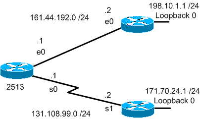
For every network configured with ip default-network, if a router has a route to that network, that route is flagged as a candidate default route. This network diagram displays the routing table taken from router 2513:
2513#show ip route

Codes: C - connected, S - static, I - IGRP, R - RIP, M - mobile, B - BGP
       D - EIGRP, EX - EIGRP external, O - OSPF, IA - OSPF inter area
       N1 - OSPF NSSA external type 1, N2 - OSPF NSSA external type 2
       E1 - OSPF external type 1, E2 - OSPF external type 2, E - EGP
       i - IS-IS, su - IS-IS summary, L1 - IS-IS level-1, L2 - IS-IS level-2
       ia - IS-IS inter area, * - candidate default, U - per-user static route
       o - ODR, P - periodic downloaded static route

Gateway of last resort is not set

     161.44.0.0/24 is subnetted, 1 subnets
C       161.44.192.0 is directly connected, Ethernet0
     131.108.0.0/24 is subnetted, 1 subnets
C       131.108.99.0 is directly connected, Serial0
S    198.10.1.0/24 [1/0] via 161.44.192.2
Note the static route to 198.10.1.0 via 161.44.192.2 and that the gateway of last resort is not set. If you configure ip default-network 198.10.1.0, the routing table changes to this:
2513#show ip route

Codes: C - connected, S - static, I - IGRP, R - RIP, M - mobile, B - BGP
       D - EIGRP, EX - EIGRP external, O - OSPF, IA - OSPF inter area
       N1 - OSPF NSSA external type 1, N2 - OSPF NSSA external type 2
       E1 - OSPF external type 1, E2 - OSPF external type 2, E - EGP
       i - IS-IS, su - IS-IS summary, L1 - IS-IS level-1, L2 - IS-IS level-2
       ia - IS-IS inter area, * - candidate default, U - per-user static route
       o - ODR, P - periodic downloaded static route

Gateway of last resort is 161.44.192.2 to network 198.10.1.0

     161.44.0.0/24 is subnetted, 1 subnets
C       161.44.192.0 is directly connected, Ethernet0
     131.108.0.0/24 is subnetted, 1 subnets
C       131.108.99.0 is directly connected, Serial0
S*   198.10.1.0/24 [1/0] via 161.44.192.2
R1#
2513#show ip protocols
2513#
The gateway of last resort is now set as 161.44.192.2. This result is independent of any routing protocol, as shown by the show ip protocols command at the bottom of the output.
You can add another candidate default route by configuring another instance of ip default-network:
2513#configure terminal
Enter configuration commands, one per line.  End with CNTL/Z.
2513(config)#ip route 171.70.24.0 255.255.255.0 131.108.99.2
2513(config)#ip default-network 171.70.24.0
2513(config)#^Z

2513#show ip route

Codes: C - connected, S - static, I - IGRP, R - RIP, M - mobile, B - BGP
       D - EIGRP, EX - EIGRP external, O - OSPF, IA - OSPF inter area
       N1 - OSPF NSSA external type 1, N2 - OSPF NSSA external type 2
       E1 - OSPF external type 1, E2 - OSPF external type 2, E - EGP
       i - IS-IS, su - IS-IS summary, L1 - IS-IS level-1, L2 - IS-IS level-2
       ia - IS-IS inter area, * - candidate default, U - per-user static route
       o - ODR, P - periodic downloaded static route

Gateway of last resort is 161.44.192.2 to network 198.10.1.0

     171.70.0.0/16 is variably subnetted, 2 subnets, 2 masks
S       171.70.0.0/16 [1/0] via 171.70.24.0
S       171.70.24.0/24 [1/0] via 131.108.99.2
     161.44.0.0/24 is subnetted, 1 subnets
C       161.44.192.0 is directly connected, Ethernet0
     131.108.0.0/24 is subnetted, 1 subnets
C       131.108.99.0 is directly connected, Serial0
S*   198.10.1.0/24 [1/0] via 161.44.192.2
After the ip default-network command was entered in the output above, the network was not flagged as a default network.
The ip default-network command is classful. This means that if the router has a route to the subnet indicated by this command, it installs the route to the major net. The ip default-network command must be issued again, using the major net, in order to flag the candidate default route.
2513#configure terminal
Enter configuration commands, one per line. End with CNTL/Z.
2513(config)#ip default-network 171.70.0.0
2513(config)#^Z

2513#show ip route

Codes: C - connected, S - static, I - IGRP, R - RIP, M - mobile, B - BGP
       D - EIGRP, EX - EIGRP external, O - OSPF, IA - OSPF inter area
       N1 - OSPF NSSA external type 1, N2 - OSPF NSSA external type 2
       E1 - OSPF external type 1, E2 - OSPF external type 2, E - EGP
       i - IS-IS, su - IS-IS summary, L1 - IS-IS level-1, L2 - IS-IS level-2
       ia - IS-IS inter area, * - candidate default, U - per-user static route
       o - ODR, P - periodic downloaded static route

Gateway of last resort is 171.70.24.0 to network 171.70.0.0

 *   171.70.0.0/16 is variably subnetted, 2 subnets, 2 masks
S*      171.70.0.0/16 [1/0] via 171.70.24.0
S       171.70.24.0/24 [1/0] via 131.108.99.2
     161.44.0.0/24 is subnetted, 1 subnets
C       161.44.192.0 is directly connected, Ethernet0
     131.108.0.0/24 is subnetted, 1 subnets
C       131.108.99.0 is directly connected, Serial0
S*   198.10.1.0/24 [1/0] via 161.44.192.2
There are still no IP protocols running here.
Gateways of last resort selected using the ip default-network command are propagated differently depending on which routing protocol is propagating the default route.
For IGRP and EIGRP to propagate the route, the network specified by the ip default-network command must be known to IGRP or EIGRP. This means the network must be an IGRP- or EIGRP-derived network in the routing table.
RIP advertises a route to 0.0.0.0 if a gateway of last resort is selected using the ip default-network command.
The default route announced using the ip default-network command is not propagated by Open Shortest Path First (OSPF).
When a network is flagged as a default, that flag stays with the route as it passed from neighbor to neighbor by RIP or IGRP.
Creating a static route to network 0.0.0.0 0.0.0.0 is another way to set the gateway of last resort on a router.
As with the ip default-network command, using the static route to 0.0.0.0 is not dependent on any routing protocols. However, ip routing must be enabled on the router.
Note: IGRP does not understand a route to 0.0.0.0. Therefore, it cannot propagate default routes created using the ip route 0.0.0.0 0.0.0.0 command. Use the ip default-network command to have IGRP propagate a default route.
In earlier versions of RIP, the default route created using the ip route 0.0.0.0 0.0.0.0 was automatically advertised by RIP routers.
In Cisco IOS Software Release 12.0T and later, RIP does not advertise the default route. It may be necessary to redistribute the route into RIP.
This is an example of configuring a gateway of last resort using the ip route 0.0.0.0 0.0.0.0 command:
router-3#configure terminal
   Enter configuration commands, one per line. End with CNTL/Z.
   router-3(config)#ip route 0.0.0.0 0.0.0.0 170.170.3.4
   router-3(config)#^Z
   router-3#

   router-3#show ip route
   Codes: C - connected, S - static, I - IGRP, R - RIP, M - mobile, B - BGP
   D - EIGRP, EX - EIGRP external, O - OSPF, IA - OSPF inter area
   N1 - OSPF NSSA external type 1, N2 - OSPF NSSA external type 2
   E1 - OSPF external type 1, E2 - OSPF external type 2, E - EGP
   i - IS-IS, L1 - IS-IS level-1, L2 - IS-IS level-2, * - candidate default
   U - per-user static route, o - ODR

Gateway of last resort is 170.170.3.4 to network 0.0.0.0

 170.170.0.0/24 is subnetted, 2 subnets
   C 170.170.2.0 is directly connected, Serial0
   C 170.170.3.0 is directly connected, Ethernet0
   S* 0.0.0.0/0 [1/0] via 170.170.3.4
   router-3#
   router-3#
How to choose the route among multiple networks as candidate default routes:
If you configure multiple networks as candidate default routes using the ip default-network command, the network that has the lowest administrative distance is chosen as the network for the gateway of last resort.
If all the networks have the same administrative distance then the network listed first in the routing table (show ip route lists the routing table) is chosen as the network for the gateway of last resort.
If you use both the ip default-network and ip route 0.0.0.0 0.0.0.0 commands to configure candidate default networks, and the network used by the ip default-network command is known statically, the network defined with the ip default-network command takes precedence and is chosen for the gateway of last resort.
Otherwise if the network used by the ip default-network command is derived by a routing protocol, the ip route 0.0.0.0 0.0.0.0 command, which has a lower administrative distance, takes precedence and is chosen for the gateway of last resort.
If you use multiple ip route 0.0.0.0 0.0.0.0 commands to configure a default route, traffic is load-balanced over the multiple routes.